
What are insertion loss and return loss?
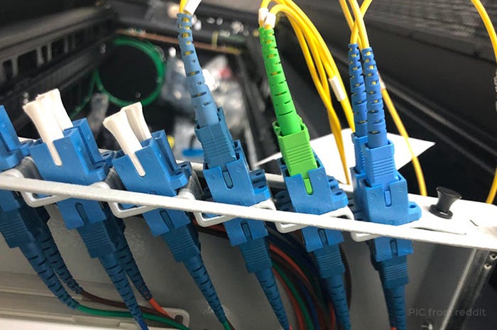
In the figure below, how much insertion loss and return loss do you think will cause? In other words, whether such a connection can guide fiber light to pass normally.
In fiber optic communications, insertion loss and return loss are two important indicators for evaluating the quality of the termination between fiber optic equipments (such as fiber optic connectors, fiber jumpers and pigtails).
What is insertion loss?
Insertion loss is mainly refers to measuring the optical loss between two fixed points in the fiber. It is the optical power loss caused by the intervention of optical devices in the optical fiber link. Its unit is dB.
Calculation formula: IL=-10 lg(Pout /Pin), Pout is the output optical power, Pin is the input optical power.
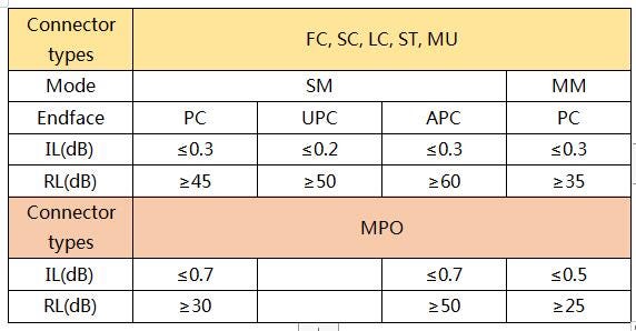
The smaller the value of insertion loss, the better the performance. For example, the insertion loss is 0.3dB better than 0.5dB. Generally, the difference in attenuation (less than 0.1 dB) between fusion splicing and manual connection is smaller than the difference in attenuation between fiber optic connectors. Here is some recommended maximum dB loss for data center fiber cabling: LC multimode fiber connector is maximum 15dB; LC single mode connector is maximum 15dB; MPO/MTP multimode fiber connector is maximum 20dB; MPO/MTP single mode fiber connection is maximum 30dB.
What is return loss?
When optical fiber signals enter or leave optical equipment components (such as optical fiber connectors), discontinuities and impedance mismatches will cause reflections or echoes. The power loss of the reflected or returned signal is the return loss (abbreviated as RL). Insertion loss is mainly the signal value measured when the optical link encounters loss, and return loss is the loss value of the reflected signal measured when the optical link encounters component access.
Calculation formula: RL=-10 lg (P0/P1), P0 represents the reflected optical power, and P1 represents the input optical power.
The return loss value is expressed in dB and is usually a negative value, so the larger the return loss value, the better. Typical specifications range from -15 to -60 dB. According to industry standards, the return loss of Ultra PC polished fiber optic connectors should be larger than 50dB, and the return loss of bevel polished is usually larger than 60dB. The PC type should be larger than 40dB. For multimode fiber, the typical RL value is between 20 and 40 dB.
What causes the IL/RL?
The quality and cleanliness of fiber endface
The defects of fibe endface (such as scratches, pits, cracks) and particle contamination will directly affect the performance of the connector, resulting in poor IL/RL. Even tiny dust particles on the core of a 5 micron single-mode fiber may eventually block the optical signal, resulting in signal loss.
The fiber is disconnected or the connection is poor
Sometimes, although the fiber is damaged, it can still guide the light through. In this case, it also leads to bad IL or RL. As shown in the picture at the beginning of this article, the APC connector is connected to the PC connector, one is at an angle of 8° and the other is the grinding angle of the micro-arc. When the two are connected, light may pass through in a short time. But at the same time, this will also result in greater insertion loss and lower return loss, which may also result in the two fiber end faces not being accurately docked, and the light cannot pass normally.
Exceeding the bending radius
Fibers can be bent, but too much bending can also cause a significant increase in optical loss and can also directly cause damage. Therefore, when it is necessary to wind the fiber, it is recommended to keep the radius as large as possible. It is generally recommended not to exceed 10 times the diameter of the jacket. Therefore, for a jumper with a jacket of 2 mm, the maximum bending radius is 20 mm.
About HYC Co., Ltd
HYC can provide customized high-quality optical fiber connectors, optical fiber jumpers and other optical connection products according to customer needs. Founded in 2000, HYC has more than 20 years of OEM/ODM manufacturing experience in optical communication devices. The main products include high-density optical connectivity, PLC optical splitters, WDM wavelength division multiplexers, MEMS optical switches and other products, which are widely used in FTTx, telecommunications, 5G networks, data centers and other fields.

A Comprehensive Overview of APON,BPON,EPON,GPON
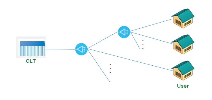
PON stands for passive optical network, which means that the ODN (optical distribution network) between the OLT (optical line terminal) and the ONU (optical network unit) does not have any active equipment, and only uses optical fibers and passive components.PON mainly uses a point-to-multipoint network structure, which is the main technology to realize FTTB / FTTH.
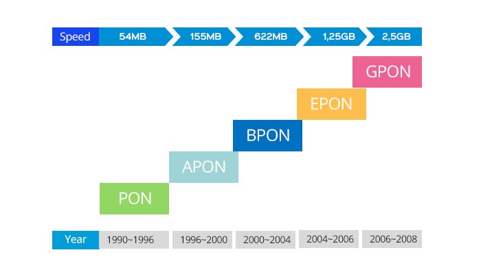
PON technology contains a lot of content, and iteratively updated constantly. The development of xPON technology ranges from APON, BPON, to later GPON and EPON. All of them were developed with different transmission modes and standards in different periods.
What is APON?
In the late 1990s, ITU (International Telecommunication Union) first proposed APON for packet communication using asynchronous transmission mode (ATM). APON uses the centralized and statistical multiplexing of ATM, combined with the sharing effect of passive splitters on optical fiber and optical line terminals, making the cost 20-40% lower than traditional PDH / SDH access systems based on circuit switching.
What is BPON?
With the rapid development of Ethernet technology, APON is basically no longer used. At this time, the concept of broadband passive optical network (BPON) was proposed. BPON is an enhanced version of APON. It was originally called APON, but it was later distinguished from APON as BPON. BPON is based on the ATM protocol, with upstream and downstream speeds of 155 and 622 Mbps, respectively, while adding dynamic bandwidth allocation and protection functions. It can provide services such as Ethernet access, video transmission and high-speed leased lines.
What is EPON?
Due to the high cost of BPON deployment, it was later replaced by EPON, with higher cost performance and faster speed. EPON is an Ethernet passive optical network. EPON is based on the PON technology of Ethernet, which combines the advantages of PON technology and Ethernet technology. It adopts point-to-multipoint structure and passive optical fiber transmission, and can provide various services on top of Ethernet. Due to the cost-effective deployment of EPON, it is the most effective communication method to realize the "three networks in one" and "last mile".
What is GPON?
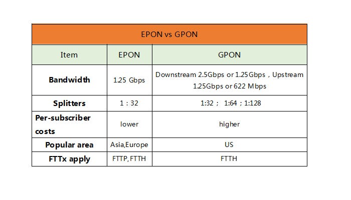
GPON is Gigabit-capable Passive Optical Network. The standards adopted by EPON and GPON are different. It can be said that GPON is more advanced and can transmit more bandwidth. Although GPON has advantages over EPON at high rates and multiple services, GPON's technology is more complex and its cost is higher than EPON. Therefore, at present, EPON and GPON are technologies with more PON broadband access applications. Which technology to choose depends more on the cost of optical fiber access and business requirements. GPON will be more suitable for customers with high bandwidth, multi-service, QoS and security requirements and ATM technology as the backbone. The future development is higher bandwidth. For example, EPON / GPON technology has developed 10 G EPON / 10 G GPON, and the bandwidth will be further improved.
As the demand for network providers' capacity continues to increase, the versatility of access networks must also be expanded to meet this growing demand. PON is the most widely used technology in FTTH. The advantage of PON technology is that it can reduce the occupation of backbone optical fiber resources and save investment; the network structure is flexible and the expansion ability is well; the failure rate of passive optical devices is low, and it is not easy to be interfered by the external environment; the business supportability is strong.
HYC Co., Ltd has 20 years of OEM / ODM manufacturing experience in the optical communication industry and has a certain influence in the global industry. It focuses on providing customers with one-stop customization of optical passive devices design, development, and manufacturing. We has production lines including optical fiber connectors, optical fiber jumpers, PLC splitters, WDM, MEMS optical switches, and products are widely used in FTTH, Data center, 5G network, Telecom, etc.

MEMS Optical Devices — MEMS OXC
Application of OXC
Optical cross connect (OXC) is a matrix switch usually with N×N ports. The OXC can be used to construct a CDC ROADM (Colorless, Directionless, and Contentionless Reconfigurable Optical Add/Drop Multiplexer), as shown in Fig.1.
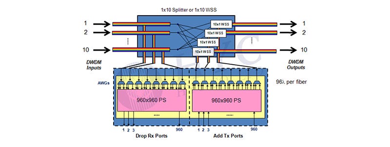
Fig.1 CDC ROADM based on WSS and OXC
OXC Constructed by 1×N Optical Switches
The OXC can be constructed by 1×N optical switches, as shown in Fig.2. It requires 2N 1×N optical switch to construct a N×N OXC. Thus the size and cost of the OXC module increase rapidly with the incensement of port number N. OXC of this structure is usually limited to below 32×32 ports.
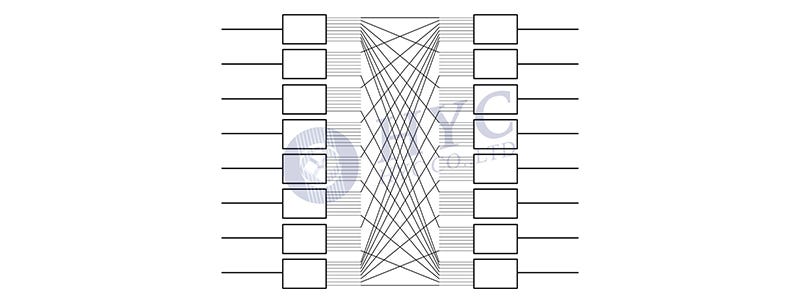
Fig.2 An 8×8 OXC constructed by sixteen 1×8 optical switch
OXC based on 2D MEMS
The second approach for a OXC is a cross-bar optical switch based on a MEMS mirror array. In 1996, H. Toshiyoshi and H. Fujita from University of Tokyo reported the first cross-bar MEMS optical switch with potential for matrix scaling up, as shown in Fig.3. The reported device has two inputs and four outputs. The switching is realized with four mirrors. Each mirror has two states, lying horizontally (Off-state) to let pass the optical beam or standing vertically (On-state) to reflect the optical beam .
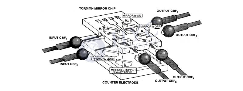
Fig.3 Structure of the first cross-bar matrix switch based on MEMS torsion mirror
The SEM photos and structure of the MEMS torsion mirror for above cross-bar optical switch is shown in Fig.4. The mirror is supported by a polysilicon beam. It stays horizontally when no electrical voltage is applied to the electrodes and stands vertically when driven by electrostatic force .
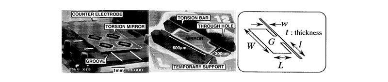
Fig.4 SEM photos and structure of the MEMS torsion mirror
L.Y. Lin, et. al., reported the first 2D MEMS matrix switch, as shown in Fig.5. A N×N mirror array is required for a N×N optical switch. All the optical paths are in a 2D plane, which is why it is call 2D MEMS optical switch.

Fig.5 Structure of the first 2D MEMS matrix switch
The switching is realized by micro-actuated mirrors as shown in Fig.6. The mirror is hinged on the base. Two pushrods are designed to hinge the mirror on one end and a translation plate on the other end. The translation plate is driven by a scratch drive actuator and pulls the mirror forward. The mirror rotates when it is pulled.
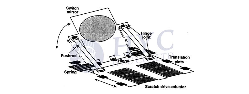
Fig.6 Schematic drawing of the micro-actuated mirror
In 2002, Li Fan et. al. from OMM, Inc. reported a MEMS mirror array for matrix switch, as shown in Fig.7.
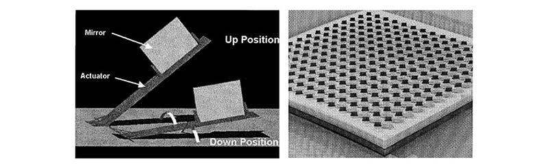
Fig.7 2D MEMS mirror array by Li Fan et. al. from OMM, Inc.
The 2D MEMS matrix switches are characterized by simple structure and easy assembly, while their scalability is limited. As we can see in Fig.5, the lengths of light paths for different links are quite different, which introduces coupling loss and loss uniformity. The tolerance to light path difference depends on the beam size in the free space optics. An optical beam with small radius ω0 is more divergent according to Eq. (1) and the collimation length is shorter according to Eq. (2).

The coupling between two single mode fibers (SMF) is shown in Fig.8(a). The coupling loss increases rapidly with the increment of the separation between the two fibers. The separation between two SMF is limited to <20μm. In order to increase the fiber separation to accommodate free space optics, thermally expanded core (TEC) fibers and lensed fibers are employed, as shown in Fig.8(b) and Fig.8(c), respectively. The TEC fibers and lensed fibers expand the beam size for free space transmission. The separation between two TEC fibers is ~10mm and that between two lensed fibers is ~50mm. For some applications that require longer free space light paths (such as 3D MEMS optical switches to be mentioned below), the collimating lenses are required, as shown in Fig.8(d).
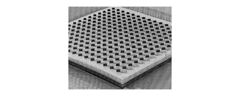
Fig.8 Fiber coupling methods
Thus we know, with the employment of TEC fibers or lensed fibers in a 2D MEMS optical switch, the free space light paths are extended to accommodate more MEMS mirrors and thus the optical switch is scaled up. However, the maximum beam size is limited by the mirror size, which depends on the MEMS design and process. The mirror size is usually required to be Ф>3ω0 to reflect >99% of the optical power. Thus the maximum number of ports is usually limited to be 32×32 for a 2D MEMS optical switch.
OXC based on 3D MEMS
In order to further scale up the OXC, 3D MEMS optical switches are developed. The basic structure of a 3D MEMS OXC by NTT Laboratories is shown in Fig.9, which consists of two MEMS mirror arrays and two 2D fiber collimator arrays. Each input fiber collimator corresponds to one mirror in the first MEMS mirror array and each output fiber collimator corresponds to one mirror in the second MEMS mirror array. All the mirrors on the MEMS chips have two rotation axes, as shown in Fig.10 .
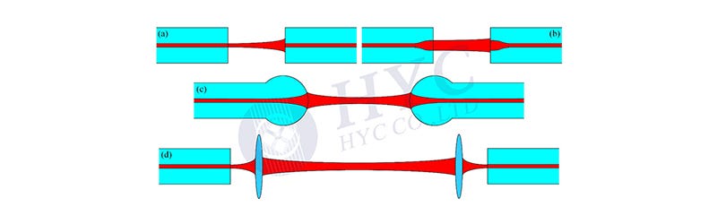
Fig.9 Basic structure of a 3D MEMS OXC by NTT Laboratories
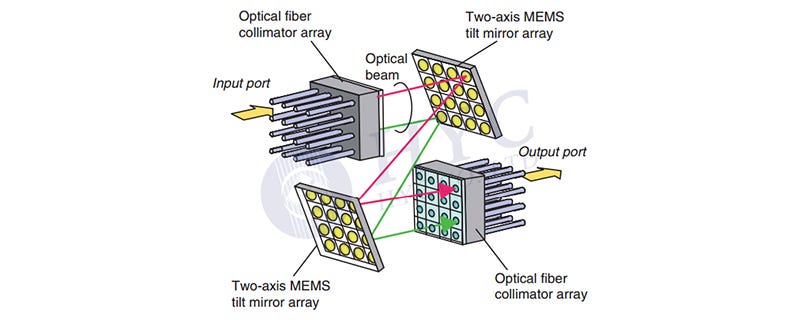
Fig.10 SEM photos of the MEMS mirror array and single mirror with two axes
The optical beam from each input is independently controlled by a mirror in the first MEMS chip and is directed to another mirror (corresponding to the destination output) in the second MEMS chip. The second mirror rotates around two axes and adjusts the reflected beam toward the output fiber collimator. Thus by control of the two MEMS chips, optical signal from any input can be switched to any output. The 3D MEMS OXC was fabricated by NTT laboratories in Oct., 2003. The photo of the sample is shown in Fig.11.
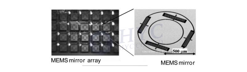
Fig.11 3D MEMS OXC sample fabricated by NTT Laboratories
V. A. Aksyuk et. al. from Bell Laboratories reported a 3D MEMS OXC in Apr., 2003, which was prior to the OXC reported by NTT laboratories. We first mentioned the latter because of its simple structure and ease for analysis. The OXC structure and sample by Bell Labs are shown in Fig.12 and Fig.13, respectively. It includes two MEMS mirror arrays, two 2D fiber arrays and one Fourier lens. Each input-output link is constructed through one mirror in the first MEMS chip and another mirror in the second MEMS chip.
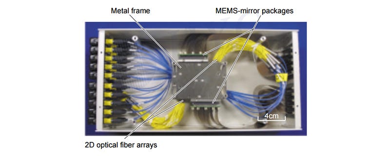
Fig.12 Structure of the 3D MEMS OXC by Bell Laboratories
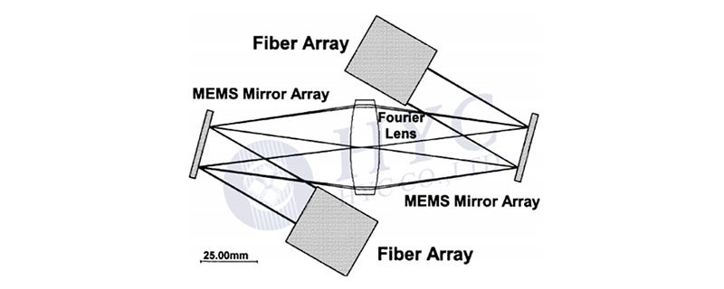
Fig.13 Photo of the 3D MEMS OXC by Bell Laboratories
In 2012, Yuko Kawajiri et. al. from NTT labs reported another 3D MEMS OXC, as shown in Fig.14 and Fig.15. A toroidal concave mirror is employed instead of a Fourier lens. The toroidal design of the concave mirror is to reduce the off-axis aberration of edge ports .
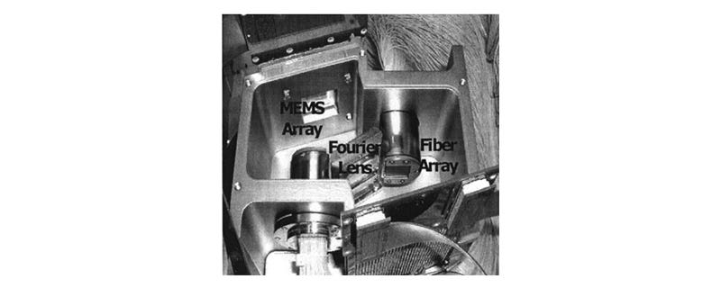
Fig.14 Structure of the 3D MEMS OXC by NTT Laboratories

Fig.15 Photo of the 3D MEMS OXC by NTT Laboratories
The principles of OXC in Fig.12 and Fig.14 are similar. Comparing to the structure in Fig.9, the beam size in free space optics is larger and thus loss is reduced. What’s more, the structure in Fig.9 require that the MEMS mirrors have larger rotation angle, which adds to difficulty for MEMS design.
About HYC
HYC Co., Ltd was founded in 2000. It is a leading passive optical devices OEM/ODM manufaturer in the global industry, focusing on R&D, manufacturing, sales and service of passive devices for optical communication. The company's main products are: optical fiber connectivity products, WDM wavelength division multiplexers, PLC optical splitters, and MEMS optical switches, which is widely used in 4G / 5G networks, Telecom, Data centers, etc.
http://www.hyc-system.com

What is CCWDM(Compact Coarse Wavelength Division Multiplexing)?
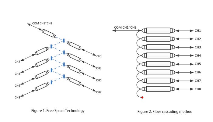
CCWDM is Compact CWDM (Compact Coarse Wavelength Division Multiplexing), which is a wavelength division multiplexing technology based on TFF (Thin Film Filter). It works in the same way as CWDM modules, except that CCWDM uses free space technology (As shown in Figure 1), compared with the common CWDM fiber cascading method (as shown in Figure 2). The package size of CCWDM is smaller than CWDM and with lower insertion loss and better consistency. CCWDM can be used to replace the CWDM products in telecommunications, corporate networks, PON networks, cable TV and other fields. The lower insertion loss makes the CCWDM module have lower signal attenuation when used, thereby reducing the power requirements of the signal transmitter.
HYC's CCWDM module uses free space technology to transmit optical signals by using an independent sealed space. The working mode is the same as CWDM, first input(output) signal from the COM terminal, and then output (input) optical signal through TFF (film filter) for other port transmission. CCWDM module can save more space by using parallel optical path cascading of free space technology different from CWDM optical fiber cascading method. HYC’s CCWDM module has mature production technology and stable and reliable performance. It supports an ambient temperature of -40 ~ + 85 ° C to ensure stable transmission of signals.
About HYC Co., Ltd
Founded in 2000, HYC CO., LTD (HYC) is the world’s leading passive optical devices OEM/ODM manufacturer who engages in R&D, producing, marketing and providing service of fiber optical products.
Our main products are: Optical Fiber Connector, WDM, PLC splitter, MEMS optical switch and other optical passive basics devices. HYC products and solutions are widely used in 4G/5G, Telecom, Data Center, Cloud Computing industry and other fields.
www.hyc-system.com
?)
HYC New Production Building Successfully Capped
On March 31, with the pouring of the last piece of concrete, the main body structure of the HYC new production base was successfully capped. At present, the architectural configuration of new production building of the first phase project was taken shape. This is a brand new milestone of the whole HYC new industry park project.
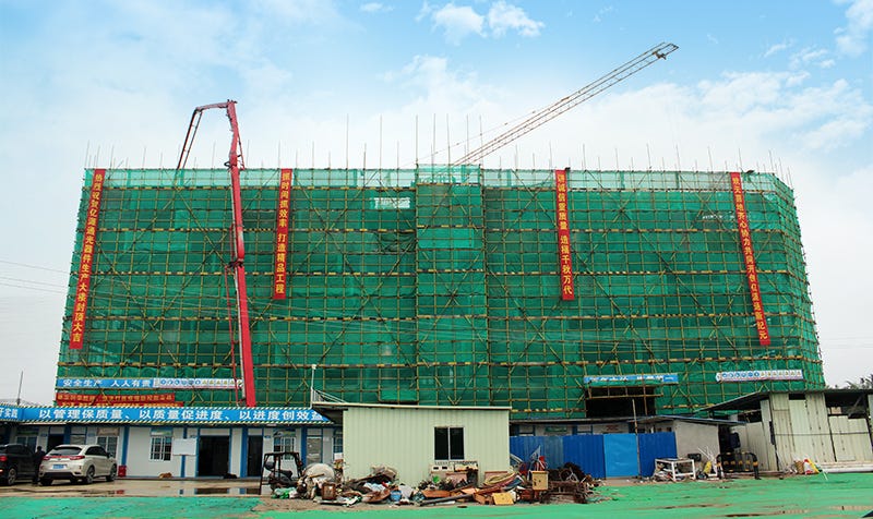
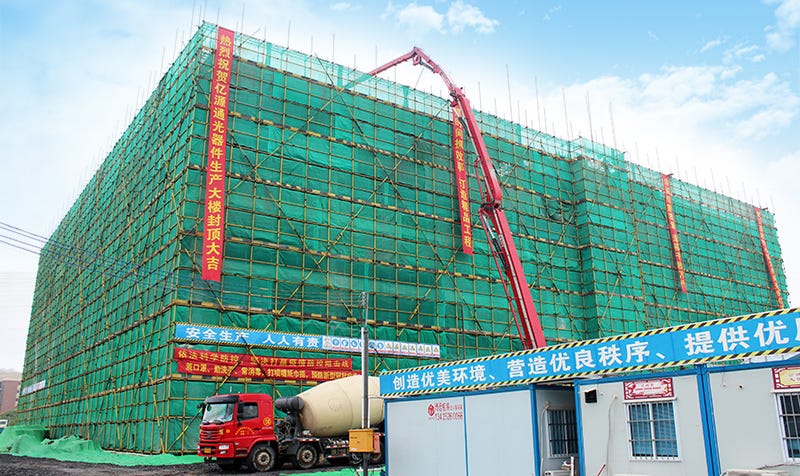
Project is located in Qingyuan city, Guangdong Province, a total construction area of 40,000 square meters, and is composed of five-story multi-storey buildings. It is invested with 130 million yuan. Since July 2019, when the first phase project started construction, construction of HYC new industry park has been progressing steadily according to the schedule, with all projects moving forward smoothly. Now the main concrete structure of the production building was capped.

The completion of the HYC device production base, which carries the dreams of all HYC people, will help HYC greatly enhance its production capacity, R&D innovation ability and market core competitiveness, so as to better serve the society, and to start a whole new chapter with a brand new look. Let's look forward to the early completion of HYC beautiful new home!
About HYC
Founded in 2000, HYC CO., LTD (HYC) is the world’s leading passive optical devices OEM/ODM manufacturer who engages in R&D, producing, marketing and providing service of fiber optical products.
Our main products are: Optical Fiber Connector, WDM, PLC splitter, MEMS optical switch and other optical passive basics devices. HYC products and solutions are widely used in 4G/5G, Telecom, Data Center, Cloud Computing industry and other fields.
www.hyc-system.com

What is optical splitter and its important technical indicators?
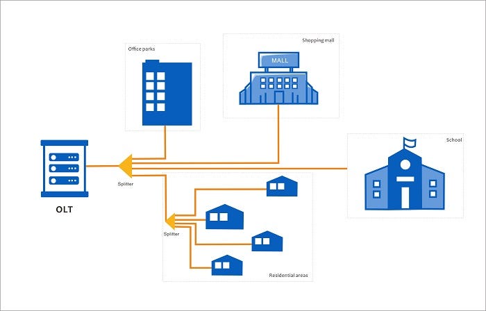
Optical splitter is one of the important passive devices in optical fiber link. It is mainly to implement the optical signal splitting between the optical line terminal OLT and the optical network terminal ONU in the passive optical network.
The optical splitter enables the signal on the optical fiber to be distributed between two or more optical fibers with different separation configurations, such as 1×2, 1×4, 1×N, or 2×4, M×N. The general architecture of FTTH is: OLT (Machine room office end) -- ODN (Passive optical network distribution system) -- ONU (User end). An optical splitter is used in ODN to realize that multiple end users share a PON interface. In the PON network, when buildings are scattered and irregular, such as villas, with long distances and low user density, the centralized light splitting method can make full use of resources and cover the surroundings.
In a passive optical network, only one optical splitter can be used, or multiple optical splitters can be used together to separate optical signals.

The performance indicators that affect the optical splitter are usually as follows:
Insertion loss
The insertion loss of a fiber splitter refers to the dB of each output relative to the input optical loss. Generally, the smaller the insertion loss value, the better the performance of the splitter.
Splitting ratio
The split ratio is defined as the output power of the splitter output port in the system application. Generally, the splitting ratio of the PLC splitter is uniformly distributed, while the splitting ratio of Fused optical splitter can be unequal. The splitting ratio is related to the wavelength of the transmitted light. For example, when transmitting 1.31μm light, the splitting ratio of the two output light ends is 50:50; when transmitting 1.5 μm light, it becomes 70:30 (This happens because that optical splitter has a certain bandwidth, which is the bandwidth of the optical signal transmitted when the splitting ratio is substantially unchanged).
Isolation
Isolation refers to a light path optical splitter to other optical path of the optical signal isolation.
Return loss
Return loss, also known as reflection loss, refers to the power loss of an optical signal that is returned or reflected due to discontinuities in the fiber or transmission line. The larger the return loss, the better, to reduce the impact of reflected light on the light source and the system.
In addition, uniformity, directivity, and PDL polarization loss are also parameters that affect the performance of the beam splitter. Optical fiber splitter is one of the most important passive devices in the optical fiber link. It is particularly suitable for connecting MDF and terminal equipment to distribute optical signals in passive optical networks (EPON, GPON, BPON, FTTX, FTTH, etc.).
About HYC Co., Ltd
HYC is a leading OEM / ODM manufacturer of passive optical communication devices in the global industry, focusing on providing customers with one-stop customization service for the design, development and manufacturing of passive basic optical devices.
Our main products are: Optical Fiber Connector, WDM, PLC splitter, MEMS optical switch and other optical passive basics devices. HYC products and solutions are widely used in 4G/5G, Telecom, Data Center, Cloud Computing industry and other fields.

HYC New Product – 1×N MEMS Optical Switch
With the rapid development of optical fiber, the traditional communication devices with electricity as the core is hardly to meet the needs of high-speed and large-capacity optical communication network. MEMS optical switch has become one of the important devices in all optical communication network due to its small size, easy integration and large capacity.
MEMS optical switch is based on Micro-Electro-Mechanical System(MEMS) technology, using the micromirrors to control and switch the optical path. Its function is shown in the following figure:

MEMS is a micro-device or system which can be produced in batches by interating micro-machinery, micro-actuators, signal processing and control circuits. The principle of MEMS optical switches is very simple. When optical exchange is performed, the angle of the MEMS micro-mirror is moved or changed by the driving of electrostatic force or magnetic power, and the input light is switched to different output ends of the optical switch to realize the switching and on-off of the optical path. Its schematic diagram is shown in the following figure:

Compared with traditional mechanical optical switches, MEMS optical switches have the following advantages:
1.Small size and large exchange capacity
2.MEMS chip can be mass produced, so the single cost is not high
MEMS Optical Switch is an ideal component for OXC,MCS, system monitoring and protection, optical fiber sensing, and equipment reuse protection.

Now, HYC can provide a series of MEMS optical switches in 1×N configuration, such as 1x2, 1x4, 1x8, 1x16, 1x32, 1x48, etc. Customization is available. The general indicators are as follows:

About HYC Co., Ltd
Founded in 2000, HYC CO., LTD (HYC) is the world’s leading passive optical devices OEM/ODM manufacturer who engages in R&D, producing, marketing and providing service of fiber optical products.
Our main products are: Optical Fiber Connector, WDM, PLC splitter, MEMS optical switch and other optical passive basics devices. HYC products and solutions are widely used in 4G/5G, Telecom, Data Center, Cloud Computing industry and other fields.

Structure of All Optical Network Based on CDC-ROADM Technology
Above is the past four stages of optical fiber communication. 5G is the focus of the world in recent years, which is characterized by high speed, large capacity and low delay. The wireless technologies have enabled the former two. However, the delay of 5G is related to the optical fiber network supporting the base stations. The high speed and wide connection of terminals exhausts the bandwidth of optical fiber communication and results in more delay. The optical fiber network is required to be upgraded and the focus is on metro network. Based on cost consideration, the current metro network is mainly based on CWDM and FOADM (fixed optical add/drop multiplexer) technologies. The DWDM and ROADM technologies for long haul network are expected to sink to metro network.
Structure of All Optical Network
In order to improve the efficiency and reduce the OPEX (operation expense) cost of the optical fiber network, the new generation of all optical network (AON) is required to be software defined network (SDN). The SDN network can be reconfigured based on software setting, exempting from manual operation. ROADM is the key equipment enabling SDN network, as shown in Fig.1. The ROADM-based AON includes three level of networks: long haul, metro and access network. The long haul network connects big cities and is usually constructed as a mesh network. The metro network usually employs fiber ring structure. As the telecom services become diverse and complicated, the metro network extends to be a multiple-ring network, including a core ring and many edge rings. The access network is fed by the metro rings and extends to the vicinity of the end users. The final links between the access network and the users include FTTx (to the business buildings, schools, homes, etc.) and wireless base stations.
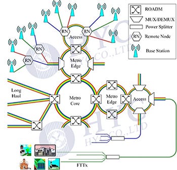
Fig.1 Structure of all optical network
What’s CDC-F ROADM?
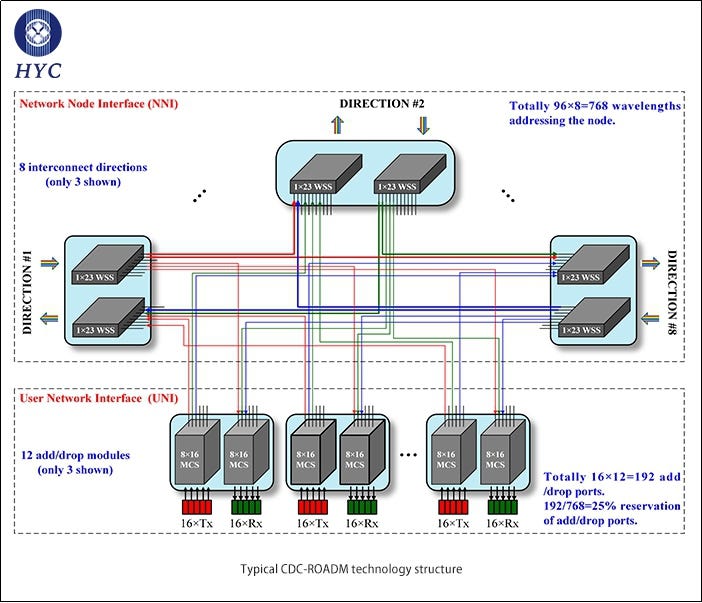
A ROADM node has a network node interface (NNI) and a user network interface (UNI). The NNI interconnects DWDM signals from/to multiple directions. The DWDM signals are switched between different directions in wavelength granularity. The UNI downloads signals designated to the node and uploads signals from the node in wavelength granularity. In order to realize non-blocking switching and adding/dropping of wavelengths, the new generation of ROADM nodes are required to be colorless, directionless and contentionless (CDC ROADM).
Considering an 8-dimentional (8D) ROADM node with 80-channel DWDM in each direction, the total wavelengths to be handled in the node is 8×80=640. However, the wavelengths to be added/dropped by the UNI of the node is usually less than 20% based on statics. Most of the wavelengths (more than 80%) are just switched by the NNI of the ROADM node. Thus 640×20%=128 add/drop ports are enough for the UNI. However, 20% reserve of add/drop ports requires each port to be versatile, which means that each add/drop port can add/drop different wavelengths from different directions (colorless and directionless) according to allocation by the control system. Meanwhile, the UNI needs to be capable to simultaneously drop the same wavelengths from different directions (contentionless).
The signals transmitting in the optical fiber may have different bit rates. In high-speed transmission system, signals with different bit rates need different channel width due to the sideband originating from modulation. As shown in Fig.2, signals with bit rates of 100G, 400G and 1T need channel width of 50GHz, 75GHz and 150GHz, which is quite different from low-speed (≤25G) signals. Low-speed signals usually occupy channel width of 50GHz or 100GHz, depending on the design of DWDM system.
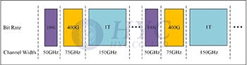
Fig.2 Channel width requirement for signal of different bit rate
In order to accommodate the coming high-speed transmission, the DWDM system need to provide super-channel function. The channel width should be flexible. It can be dynamically allocated as 50GHz, 75GHz, 100GHz,150GHz, etc., according to demand. Super-channel is a term for system designer. The module designer uses another term “flexgrid” for the same meaning.
A ROADM capable of colorless, directionless and contentionless functions is called CDC ROADM. It can be further defined as a CDC-F ROADM when flexgrid function is also supported.
The coming 5G application promotes the upgrading of AON. As the key part for AON, ROADM market is expected to increase rapidly, especially in metro network application.
About HYC
HYC Co., Ltd was founded in 2000. It is a leading passive optical device OEM / ODM and solution provider in the global industry, focusing on R&D, manufacturing, sales and service of passive devices for optical communication. The company's main products are: optical fiber connectivity products, WDM wavelength division multiplexers, PLC optical splitters, and MEMS optical switches, which is widely used in 4G / 5G networks, Telecom, Data centers, etc.
http://www.hyc-system.com

How do fiber optic connectors achieve precise alignment between fibers?
When the two optical fibers are connected, due to the difference in position, shape and structure of the two optical fibers, the energy cannot be 100% transferred from one fiber to the other, that is, the connection loss will occur. The two connected fibers must be precisely aligned to ensure low loss.The main function of the optical fiber connector is to connect two optical fibers quickly, so that the optical signal can be continuous to form an optical path. How do fiber optic connectors achieve precise alignment between optical fibers?
The types of fiber optical connectors are variable. However, the basic warranty for precise alignment between optical fibers depends on two factors. The first is ceramic ferrules with precise inner diameter, outer diameter and concentricity, which is warranted by mechanical fabrication of ceramics. The second is ceramic sleeves with a cleft, which is a clever design. Fig.1 shows how two optical fibers are aligned through a ceramic sleeve. The inner diameter of sleeve is a little smaller than the outer diameter of the ferrules. The ferrules can be inserted into the sleeve because of the cleft. The expanded sleeve constricts the ferrules to ensure precise alignment.
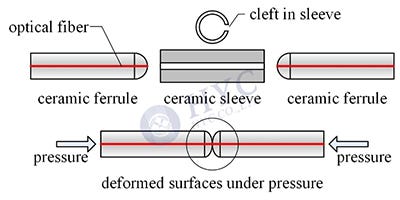
Fig.1 Alignment between two optical fibers
The core size of the single mode fiber (SMF) is about 8~10μm. The two connected fibers must be precisely aligned to ensure low loss. Fig.2 shows how much the lateral offset between two optical fibers influence the IL. The curve is exponential. A small lateral offset such as 2.4μm will introduce IL of 1dB. Thus the lateral offset between the two fibers must be kept <0.5μm for SMF fiber optic connectors.
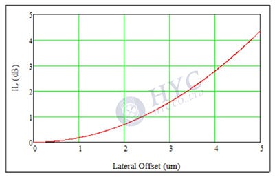
Fig.2 IL vs the lateral offset between two optical fibers
Physical Contact between Fibers
However, only precisely alignment is not enough for optical fiber connection. As we know, back reflection happens at the interface between two different medias. The refractive index (RI) of quartz fiber @1.55μm is about 1.455. Thus the BR at the fiber endface is 3.4%. The BR light will affect the performance of the communication system. Meanwhile, an IL of 0.15dB is introduced at each quartz-air surface. Thus a fiber connection will add to 0.3dB signal loss.
Anti-reflection (AR) coating is usually employed to reduce BR at interface. However, it is not considered for fiber optical connectors. Firstly, AR coating will add to the cost. Secondly, the fiber connection is not fixed. Repeated plugging is required for fiber optical connectors, which will damage the AR coating. Can we have the fiber endfaces AR coated and separated. Fig.3 shows how the longitudinal gap between two optical fibers influences the IL. A gap of 50μm will introduce an excess IL of nearly 1dB, which is intolerable in optical fiber communication system.
Thus we get the common view that the fibers must be in contact and the endfaces can’t be AR coated. BR happens at the interface between two different medias. The air between fiber endfaces must be squeezed out and thus the fiber endfaces are in physical contact (PC) as a uniform media. Because the optical fibers are fixed at the center of ceramic ferrules, any roughness on the ceramic surfaces will affect the physical contact between optical fibers. In order to keep the physical contact between fibers, the ferrule endface is spherically polished with the fiber endface at the top of the sphere, which is the second clever design. As shown in Fig.1, the ferrules are inserted into the sleeve and the endfaces are deformed under pressure. The deformation of endfaces ensures the physical contact. The physical contact depends on deformation of the endface. Ceramic material is abrasion resistant and elastic, which are why it is selected instead of glass.
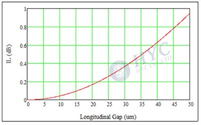
Fig.3 IL vs the longitudinal gap between two optical fibers
Further Reduction of Back Reflection
The physical contact between fibers can ensure low loss in fiber connection, while the RL is limited to about 55dB. For some applications requiring higher RL, fiber optic connectors with angled polished endface are introduced, which is called angled physical contact (APC). Fig.4 shows the relationship between the added return loss and angle of the endface. The endfaces of fiber optic connectors are usually polished by an angle of 8°, which adds to an excess RL of 36dB. Thus the total RL of APC connectors are >65dB.
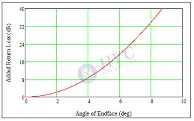
Fig.4 Relationship between the added return loss and angle of the endface
Fiber optic connectors are the most basic optical passive components for optical fiber communication systems. The basic specification requirements for them are low insertion loss (IL) and high return loss (RL), i.e. low back reflection (BR). However, as the most widely employed components, low cost and easy connection are equal important as the specifications.
About HYC
HYC Co., Ltd was founded in 2000. It is a leading passive optical device OEM / ODM and solution provider in the global industry, focusing on R&D, manufacturing, sales and service of passive devices for optical communication. The company's main products are: optical fiber connectivity products, WDM wavelength division multiplexers, PLC optical splitters, and MEMS optical switches, which is widely used in 4G / 5G networks, Telecom, Data centers, etc.
http://www.hyc-system.com

How does FBG (Fiber Bragg Grating) Optical Reflector work?
FBG fiber optic reflector, also known as Fiber Bragg Grating Filter, is usually installed on the front end of the ONU. Combined with OTDR equipment, it can realize the point-to-point (PTP) or point-to-multipoint (PTMP) network monitoring of optical link, which can reflect the network abnormality quickly and accurately.
What is FBG? FBG is Fiber Bragg Grating. A fiber grating is a type of diffraction grating. Fiber Bragg Gratings (FBG) is a simple and low-cost way to build a grating into a specific wavelength range of fiber. When broad-spectrum light is incident on the fiber with built-in grating, the wavelength matching the grating will be reflected back to the input end, and the rest of the light will be passed through to the other end. Fiber gratings have the characteristics of small size, good wavelength selectivity, good compatibility, etc. The manufacturing process for fiber gratings is mature, with good practicality and low cost, they are widely used in the field of communication and sensing and is also ideal important device in optical network.
The FBG optical reflector utilizes the wavelength selectivity of the fiber grating, and the fiber grating is embedded in the adapter. It can be conveniently installed on the front end of an optical network (ONU), and it can quickly and accurately implement optical network fault detection with the help of an optical time domain reflector (OTDR). Due to the excellent wavelength selection characteristics of fiber gratings, anti-electromagnetic interference, the center wavelength drift is small with the change of external temperature, and when the optical network coverage and depth continue to increase, the entire optical network fault point can be detected quickly and accurately.
With the application of optical splitters in passive optical network (PON) networks, the complexity of the ODN network deployment environment has been increased. The splitters at the end of the FTTx will split the trunk optical signals and increase the difficulty to identify attenuation events on ODN branch fibers. The application of fiber grating reflector is a wavelength selective reflector based on this environment, which aims to improve the fast and accurate detection of optical link failure events by OTDR.
The fiber optic reflector is usually installed on the ONU side. The OTDR detects the intensity of the optical signal reflected by this reflector and compares the return loss between the normal line and the failed link to determine whether the optical fiber in the link is damaged or not. The normal PON system working wavelength does not meet the reflector conditions then will pass through the reflector with a small attenuation. While the reflector achieves the monitoring function, but without disturbing the transmit. 1650nm fiber grating reflector, the grating reflection wavelength is 1645 ~ 1650nm. The optical signal in this Bragg wavelength range will return along the input path, and all other wavelengths of light (1260 ~ 1625nm) can pass through. If the input optical signal segment can detect the fiber grating reflection peaks in this band, it can be judged that the transmission path is normal. Otherwise, it is abnormal.
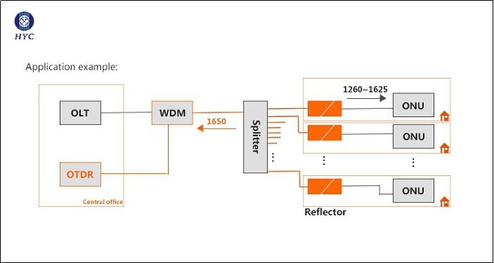
End-to-end OTDR measurement from the OLT to the ONT is usually difficult because the splitter brings high losses and complex networks. The application of fiber optic reflector is a cost-effective solution to help OTDR detection, and it is the best way to implement real-time end-to-end (OLT to ONT) monitoring of optical networks in FTTx networks.
HYC's self-developed FBG fiber optic reflector has the advantages of low insertion loss, high reflectivity, and easy installation. It is widely used in PON networks, OTDR testing, central computer room testing, FTTX and other fields. It can be customized as special pigtail or adapter type, and the connector interface is LC, SC APC / PC.
About HYC
HYC Co., Ltd is a leading OEM / ODM and solution provider of optical passive devices in the industry, focusing on R&D, design, manufacturing, sales and service of passive devices for optical communication. HYC has an international R&D and operation team, advanced automated production and testing equipment, and an information-based lean operation system, with excellent design and development capabilities, large-scale organization and production capacity, quality control capabilities, providing high stability, cost-effective, and leading technology products.
http://www.hyc-system.com
 Optical Reflector work?)
What’s the Principle of Arrayed Waveguide Grating (AWG)
AWG is Arrayed Waveguide Grating and is the technology of first choice in dense wavelength division multiplexing systems (DWDM). AWG is a planar waveguide device, which is an arrayed waveguide grating fabricated on a chip substrate using PLC technology. Compared with FBG and TTF, AWG has the advantages of high integration, multiple channels, low insertion loss, and easy batch automated production.
We begin with the principle of a concave grating to better understandard that of the AWG. The structure of a concave grating is shown in Fig.1. The gratings are aligned on a large circle with radius R=2r. There exists a small circle with radius r, which is half of the large circle. The small circle is called Rowland circle. The concave grating provides both functions of a traditional grating and a lens. Light emitting from any point P1 on the Rowland circle will be focused on another point P2 on the circle after diffraction by the concave grating. The diffraction angle θ and incident angle α are related by Eq. (1).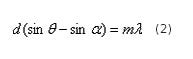
According to Eq. (1), the diffraction angle θ is wavelength dependent. When colorful light emitts from P1, different wavelengths will be focused on different points (near P2) on the Rowland circle.
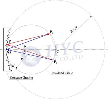
Fig.1 Diffraction in a concave grating
Now we come to discussion on the AWG. The input/output star couplers have the similar structure as the concave grating. Fig.2 shows the structure of the output star coupler. The endface of the arrayed waveguides are aligned on a large circle with radius R=2r, while the endface of the receiver waveguides are aligned on a small circle (Rowland circle) with radius r. The structure of the input star coupler is similar with the receiver waveguides substituted by one transmitter waveguide at the central position C.
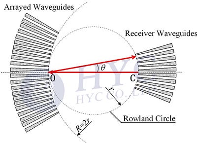
Fig.2 Structure of output star coupler
Let’s see the analogy between the concave grating and the star coupler, as shown in Fig.3. In the concave grating, colorful light emits from one point on the Rowland circle. Different wavelengths are focused on different positions on the Rowland circle. In the star coupler, DWDM signals emit from the central point C of the receiver waveguides, which is on the Rowland circle. If reflective diffraction happens in the arrayed gratings as in the concave grating, different wavelengths will be focused at different positions on the Rowland circle. Then the dispersed wavelengths are received by the receiver waveguides aligned on the Rowland circle. The key point is how can reflective diffraction happen at the arrayed grating.

Fig.3 Analogy between concave grating and star coupler
As the input/output star couplers are the similar, we can fold the AWG as Fig.4. A mirror is placed to symmetrically divide the arrayed waveguides. The left half arrayed waveguides are mirror to the right half. The input star coupler is mirrored to the output star coupler. The transmitter waveguide is mirror to the central position of the receiver waveguides. Thus the operation of the AWG can be regarded as follow. DWDM signals emit from the central position C of the receiver waveguides and are separated into the arrayed waveguides after free propagation in the output star coupler. The multiple beams propagate in the right half of the arrayed waveguides and reflected by the mirror. The reflected multiple beams emit to the output star coupler. After free propagation in the star coupler, different wavelengths are focused on different positions and are received by different receiver waveguides. Thus demultiplexing of DWDM signals is realized.
Fig.4 Folding operation of the AWG

AWG has the advantages of small wavelength interval, large number of channels, and easy integration. It is particularly suitable for ultra-high-speed and large-capacity DWDM systems. It has become the core component of most devices in DWDM systems and is widely used.
HYC launched a 48-channel Athermal Array Waveguide Grating (AAWG), which is mainly used in 400Gbps network applications. Based on the array waveguide grating technology, it does not require additional power supply or temperature control, which is a pure passive module. It has the characteristics of low loss, polarization-dependent loss, low crosstalk, and good stability in the operating temperature range of -40 °C to 85 °C.
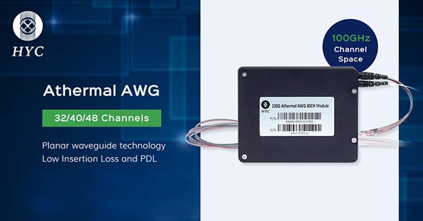
Fig.5 DWDM AAWG
About HYC
HYC Co., Ltd was founded in 2000. It is a leading passive optical device OEM / ODM and solution provider, focusing on R&D, manufacturing, sales and service of passive devices. The company's main products are: optical fiber connectivity products, WDM wavelength division multiplexers, PLC optical splitters, and MEMS optical switches, which is widely used in 4G / 5G networks, Telecom, Data centers, etc.
http://www.hyc-system.com
)
What is AWG (Arrayed Waveguide Gratings)?
Why is AWG demanded?
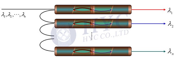
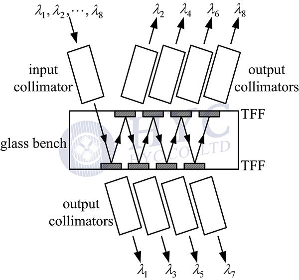
As we know, DWDM technology enables transmission of dozens of wavelengths in a single fiber, which expands the capacity of optical fiber communication enormously. The first mux/demux modules for DWDM system are based on thin-file filters (TFFs), as shown in Fig.1 and Fig.2. Both are designed in serial structure. Different wavelengths travel different number of devices in the module and result in different power loss. The loss uniformity degrades with increment of port number. Meanwhile, the maximum loss at the last port is another limitation on the port number. Thus the TFF-based WDM modules are usually limited to be ≤16 channels.
However, a typical DWDM system needs to transmit 40 or 48 wavelengths in a single fiber. Multiplexer/demultiplexer with high port number is required. A serial structure will accumulate too much loss at the last ports. Thus a parallel structure is demanded, which can multiplex/demultiplex dozens of wavelengths at the same time. Arrayed waveguide grating (AWG) is such a device.
Structure of AWG
Structure of a typical AWG is shown in Fig.3. It consists of five parts: a transmitter waveguide, an input star coupler (FPR (free propagation region) in Fig.3), arrayed waveguides, an output star coupler and dozens of receiver waveguides. The lengths of the arrayed waveguides are in arithmetic progression. Given L0 as the length of the first waveguide, the length Li of the i-th waveguide is as follow.
![]()

The DWDM signals emit from the transmitter waveguide and are separated into the arrayed waveguides after free propagation in the input star coupler. The separation is colorless, which means that all the wavelengths are separated into the arrayed waveguides identically. The arrayed waveguides generate phase difference between the multiple optical beams. The phases of the multiple beams are in arithmetic progression, which is just like the traditional gratings. Thus the different wavelengths are dispersed and then focused at different positions in the output star coupler. The receiver waveguides are set at the focusing positions. Different wavelengths are received by different waveguides and thus parallel demultiplexing of DWDM signals are realized.
Arrayed waveguide gratings (AWGs) are key components of DWDM (Dense Wavelength Division Multiplexing Systems) networks that are rapidly developing. The AWG can obtain a large number of wavelengths and channel numbers, realize multiplexing and demultiplexing of tens to hundreds of wavelengths, and can flexibly form multifunctional devices and modules with other optical devices. High stability and excellent cost performance are also one of the reasons why AWG has become the technology of choice for DWDM.
HYC launched a 48-channel (Athermal Arrayed Waveguide Grating) AAWG, mainly for 400Gbps network applications. Based on the array waveguide grating technology, it does not require additional power supply or temperature control, and is a pure passive module. It has the characteristics of low loss, polarization-dependent loss, low crosstalk, and good stability in the operating temperature range of -40 °C to 85 °C.
HYC Co., Ltd was founded in 2000, which a leading passive optical device OEM / ODM and solution provider in the global industry, focusing on R & D, manufacturing, sales and service of passive basic devices for optical communication. The company's main products are: optical fiber connectors, WDM, PLC optical splitters, and MEMS optical switches. HYC products and solutions widely applied in 4G/5G, Data Center and Cloud Computing industry etc.
?)
LC Uniboot Connector with Push-pull Tab
To meet the growing demand for transmission bandwidth, the demand for high-density cabling solutions in data centers is also increasing. HYC has designed a LC Uniboot fiber optic connector with a short push-pull tab in combination with the actual application requirements.
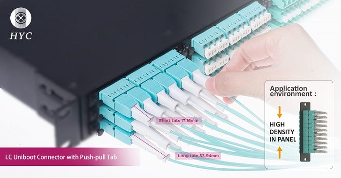
The push-pull tab is easy for inserting or removing the fiber optic connector in high-density environment without disturbing other jumpers. The short push-pull tab is not only easy for release but also save space. The Uniboot connector allows two fibers to be carried through a single jacket, which allows up to 50% savings in cabling volume. This reduces the surface area of the cable when compared to standard duplex cables, allowing this cable to facilitate improved airflow within a data center. The LC Uniboot connector polarity can be easily changed, without any tools.
Features:
The push-pull design ensure easier release from HD environment
Avoid cable twine together
Easy polarity revisable
PC/APC and Various color available
Applied to 1.2~2.5mm cable
Customized Logo is optional
IEC61754-20 and GR-326-Core complaint
RoHS/REACH&UL94-V0 inflammability complaint
Applications:
Telecom network
Ethernet network
Optical communication equipment
About HYC
HYC Co.,Ltd(HYC)is a national Hi-tech optoelectronics company engaged in R&D, manufacture and marketing of fiber optical products. Providing professional product and service for fiber connectivity,WDM, PLC splitter and high density datacom cabling.

HYC Innovative Product, 1×48 MEMS Optical Switch
The upcoming 5G application promotes the upgrade of the all-optical network (AON). As a key part of the all-optical network, the ROADM market is expected to usher in rapid growth, especially in metropolitan area networks.
MEMS optical switch is one of the core devices in ROADM. Optical switch is a kind of optical path controlling device, with the ability to control and switch the optical path. MEMS fiber optic switches are based on micro-electro-mechanical system (MEMS) technology, which achieved low insertion loss and highly repeatability by rotating the mirror of MEMS chip.
Coupled with wavelength selective switch (WSS), MEMS fiber optical switches can configuration flexibility, wavelength independent (enables any wavelength to be added/dropped on any port), direction independent (receive multiple input wavelength channels in different directions), and no conflicts (the ability to download the same wavelength channel from different directions through the same switch). This is of great significance for the flexibility and low cost of network construction. A typical CDC-ROADM technology structure is shown in the figure.
With the rapid development of Internet applications the implementation of ROADM technology based on WSS (Wavelength Selective Switch) + MCS (Multi-Cast Switch) will become an ideal solution in the construction of metropolitan area networks. 1×N MEMS optical switch is an important part of MCS.
Based on the demand for existing business and the demand for future network development, HYC has launched a series of independently developed MEMS technology products, including 1×48 channel MEMS optical switch, MEMS optical switch module integrated with WDM, PLC or PD, and MCS module.
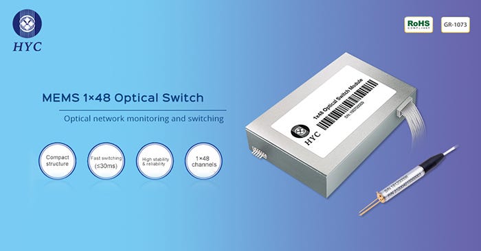
HYC’S 1×48 Optical Switch is based on MEMS (Micro Electro Mechanical System) technology and Free-space Platform. With the features of compact structure, low latency, efficient switching and other features, it is widely used in fiber monitoring system, optical add/drop system and measurement instrument system.
HYC is a leading OEM/ODM Fiber Optic Devices Manufacturers & Suppliers and provides advanced fiber optic connectors, adapters, patch cord, PLC splitter, WDM, MEMS optical switch, FTTx for data center and telecommunication networks.

Fiber Optic Patch Cable PC, APC or UPC
To make better contact between the ends of the two fibers, the ferrule end faces of the fiber optic patch cable is usually polishing into different structures. Standard polishing methods are PC, APC, and UPC. PC/APC/UPC represents the front end structure of the ceramic ferrule.
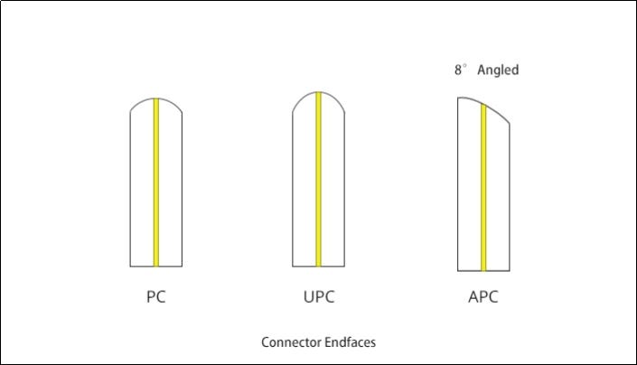
Different fiber end face finishes
PC (Physical Contact).The two end faces are polished to be slightly curved or microspherical, and the fiber core is at the highest point of the bending. This eliminates the air gap and forces the fibers into physical contact.
UPC (Ultra Physical Contact) is based on the PC to optimize the end face polishing and surface finish, the end face looks more dome-shaped. The end face of the UPC connector is not entirely flat, and there is a slight arc to achieve more accurate connecting.
APC (Angled Physical Contact). The end face of APC is usually polishing into an 8-degree angle. The 8° angled bevel makes the fiber end face tighter and reflects light through its beveled angle to the cladding instead of returning directly to the source, providing better connection performance.
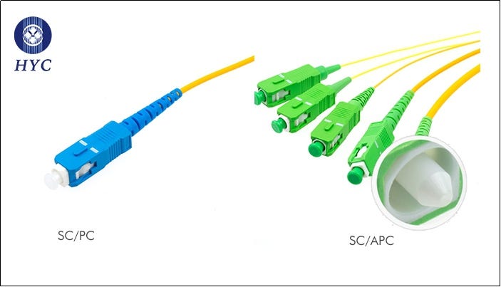
Different physical appearance
The APC fiber optic connector is usually green. UPC/PC connectors are easily identified by their blue color on the connector boot.
Insertion loss and return loss
Different polishing styles determines the quality of optical fiber, which results in different performances regarding the connector's insertion loss and return loss. Insertion loss refers to the signal loss caused by the connector or cable. In general, the typical insertion loss of PC, UPC, and APC connectors should be less than 0.3dB. Compared with APC connectors, UPC connectors are usually easier to achieve low insertion loss due to the smaller air gap. Insertion loss can also be caused by a tiny particle of dust trapped between the connector end-faces. A single dry debris particle could even damage the fibers and ferrules.
Return loss, also known as reflection loss, is a parameter representing the signal reflection performance. Usually expressed in negative dB value, the higher the value of the setting, the better. The end faces of APC connectors are beveled, so the return loss of APC connectors is usually better than UPC connectors. In general, the return loss of the PC fiber cable is -40dB. UPC return loss is higher relative to PC, generally at -55dB (or even higher). APC industry-standard return loss is -65dB. With the UPC connector, any reflected light is directly reflected back to the light source. The beveled end face of the APC connector allows the reflected light at an angle into the cladding instead of reflecting it directly to the light sources. This is the main factor that causes the return loss to differ.
Applications
PC is the most common grinding method for optical fiber connectors, which is widely used in telecommunication operator equipment. UPC is commonly used in Ethernet network equipment (such as ODF fiber distribution frames, media converters and fiber switches, etc.), digital, cable television and telephone systems. APC is generally used in optical radio frequency applications such as CATV, and also in passive optical applications, such as PON network structures or passive optical local area networks.
Connector connections need to be in the same end face structure; for example, APC and UPC cannot be mated together , because doing so will resulting in poor connector performance. However, the end faces of PC and UPC fibers are flat, and the difference is in the quality of grinding. Therefore, the mixed connection of PC and UPC will not cause permanent physical damage to the connector.
HYC has 19 years of experience in research and development of essential passive components for optical communications, supplying all kinds of fiber connectors and fiber patch cords for various specifications. HYC Co., Ltd(HYC)is, a national Hi-tech optoelectronics company engaged in R&D, manufacture, and marketing of fiber optical products. Providing professional products and services for fiber connectivity, WDM, PLC splitter, MEMS optical switch, and high-density datacom cabling. HYC products and solutions widely applied in 4G/5G, Data Center and Cloud Computing industry, etc.
http://www.hyc-system.com

Fiber Optic Component Manufacturers & Suppliers | HYC Co., Ltd
HYC is a leading OEM/ODM Fiber Optic Component Manufacturers & Suppliers and provides advanced fiber optic connectors, adapters, patch cord, PLC splitter, WDM, MEMS optical switch, FTTx for data center and telecommunication networks.
